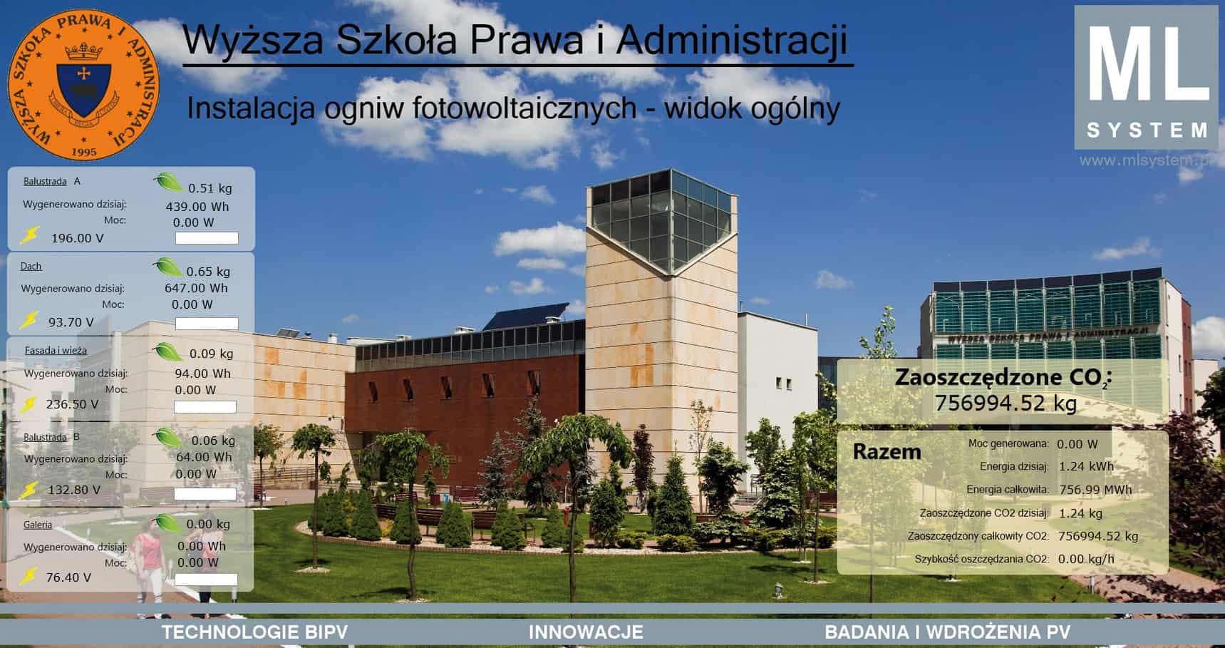
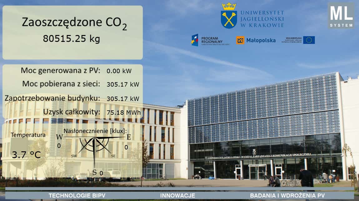
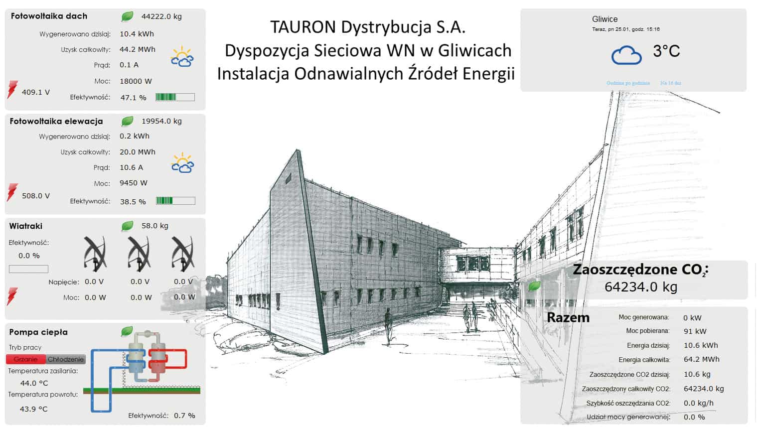
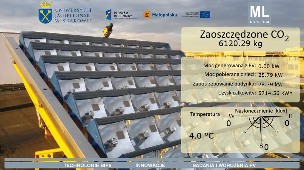
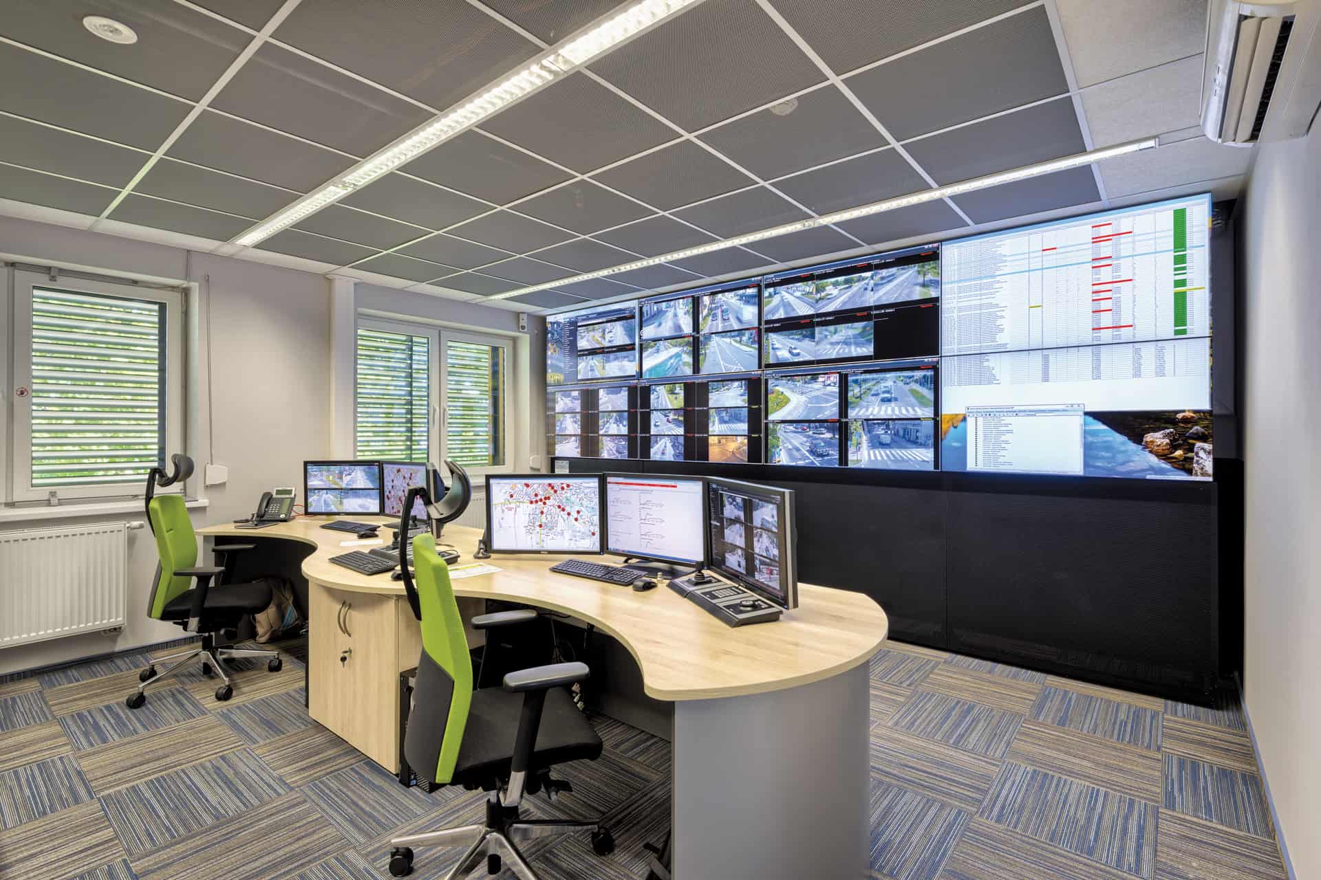
The monitoring software layer is a noteworthy element of the entire design and execution process – and often ignored. ML System carries a proprietary software suite for online visualisation of the energy gain from photovoltaic and other systems, and capable of communication with master monitoring systems. The suite provides PV system monitoring and control in the form of an Energy Management System for building technical personnel.
The EMS core is a server workstation which communicates directly with the field controllers. The field objects in the EMS can also be monitored and managed via a WLAN over TCP/IP and Ethernet. The EMS software enable real-time access to the PV system from monitoring centres. A system of user authentication passwords and system protections based on TCP/IP ensure that only authorised personnel can access specific installations. The Energy Management System synchronises the power supplied to the building power grid by controlling the power and reducing the active and reactive power in the inverter system. The EMS also supervises the operation of NoFrost heating PV modules in assigned sectors (if available). The EMS server has a centralized automated control and diagnostics cabinet. The field controllers can be communicated with via fibre-optic lines or copper lines rated at 50 Mbps.
System description: To monitor a PV system for proper performance, an Energy Management System (EMS) has been implemented. The EMS facilitates online display of energy gain from the photovoltaic system and visualises the CO2 footprint reduction relative to conventional power generation technologies (hard coal based), converted according to the standards: ISO 50001 and ISO 14064. The EMS monitoring and management is possible over TCP/IP Ethernet.
Only personnel with the proper authorisation, in the form of security passwords, may access the detailed data of the PV system. The main system component is a software suite which communicates with field controllers. Its main purpose is to collect and process the data on the operation of the PV system and devices interfaced with the PV systems, e.g. grid analysers, weather stations, PLC controllers and PV inverters. The connections between individual components of the system are based on a communication bus (network). The EMS software, which visualises the data, is server based.
Energy Management System tasks
- Status visualisation of every inverter connected to the PV system
- Energy gain visualisation
- Diagnostics of every inverter connected to the PV system
- Web-based access to the EMS interface by multiple operators
- Anonymous, password-free access to visualise the energy gain on a public website, e.g. to present the CO2 footprint reduction
- Storage of measurement and statistical data in a secure SQL database
- Integration with power grid analysers installed in the PV system
- Supervision of the PV module de-icing system, and weather-based optimisation of de-icing control (with the data from weather stations)
- PV module de-icing parameter control
- Power generation and inverter cos Ф control
- Trucker control
- Louvre control


